One of the big advantages of fiber optics is its capability for long distance high speed communications. Attenuation at long wavelengths is low. Fibers can be fusion spliced with virtually no loss. High-powered lasers and fiber amplifier regenerators mean long distances are easily obtained.
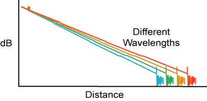
However over very long distances, new factors in fiber performance become important. Chromatic dispersion, the dispersion caused by light of different wavelengths, and polarization mode dispersion, caused by the polarization in fibers, become factors limiting fiber links. Even the variation of fiber attenuation with wavelength can become an issue. All 3 may need testing on long distance networks to ensure proper link performance.
These are NOT the only important tests - they are IN ADDITION to careful inspection of connectors and the installed cable plant (neatness and lack of stress in cables and patchcords), insertion loss testing with a source and power meter or OLTS and OTDR testing. You can review those tests in the testing pages.
Chromatic Dispersion
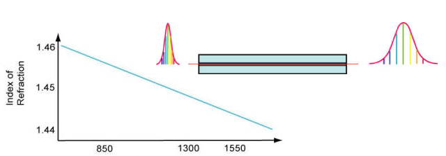
Chromatic dispersion (CD) is caused by the fact that singlemode glass fibers transmit light of different wavelengths at different speeds. The ratio of the speed of light in a medium to the speed in a vacuum defines the index of refraction or refractive index of the material. For optical fiber, the effective index of refraction is about 1.45, so the speed of light in glass is about 2/3 the speed of light in a vacuum. But the index of refraction, and thereby the speed of light in the fiber, is a function of the wavelength of light, the principle we all know from seeing a prism break light into a spectrum.
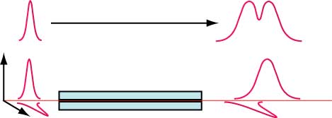
Most sources used in long distance fiber optic links are lasers which have very little spectral width. And fibers are optimized for the wavelength of use. Both these factors minimize the effects of chromatic dispersion but cannot totally stop it. As the pulse proceeds down the fiber, the light of longer wavelength travels slightly faster and spreads the pulse out as shown here.
What Causes Chromatic Dispersion
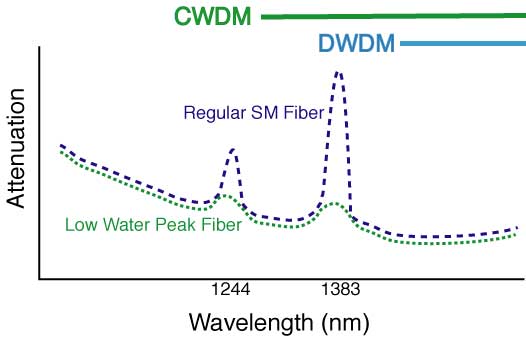
There are two factors that cause chromatic dispersion: material dispersion and waveguide dispersion. Material dispersion is caused by the variation of the index of refraction in a given material, glass in this case, over wavelength. Looking at the graph below, the variation of the index of refraction over the entire spectrum covered by fiber optics may seem small, only a few percent, but when you are dealing with very high speed pulses over very long distances it can add up.
Waveguide Dispersion
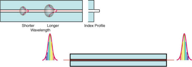
Waveguide dispersion is a bit more complex. In singlemode fiber, the wavelength of the light is not that much bigger than the core of the fiber and (we’ll leave out the complex physics) as a result the light traveling down the fiber actually travels in an area that exceeds the diameter of the core, which we call the “mode field diameter” of the fiber. The mode field diameter is a function of the wavelength of the light, with longer wavelengths traveling in a larger mode field diameter. Thus part of the light is traveling in the geometric core of the fiber and part is traveling in the cladding. Since the core is made of a higher index of refraction glass than the cladding, the light in the cladding travels faster than the light in the core. Longer wavelengths have larger mode field diameters so they suffer more material dispersion.
Engineered Dispersion in Fibers
Material and waveguide dispersion have opposite variations with wavelength, so careful design of the fiber materials and index profiles allows the fiber to have a “zero dispersion wavelength.” On either side of that wavelength, dispersion increases. The importance of chromatic dispersion is a function of the application for the fiber. As a result, different SM fibers have been developed for the requirements of specific applications. Here are a listing of the types of fibers currently in use.
| Description | ITU Spec. | Application |
|---|---|---|
| Standard Singlemode Fiber | G.652 | Original SM fiber, optimized for 1310 nm, OK for use at 1550 |
| Low Water Peak Fiber | G.652 | Processed to reduce water absorption at 1400 nm for DWDM |
| Dispersion-Shifted Fiber | G.653 | Optimized for 1550 nm |
| Cutoff Shifted Fiber | G.654 | Optimized for low loss at 1500 to 1600 nm for long haul submarine cables |
| Non-Zero Dispersion-Shifted Fiber | G.655 | Optimized for 1550 nm, DWDM |
| Wideband Non-Zero Dispersion-Shifted Fiber | G.656 | Wideband, DWDM from 1460 to 1625 nm |
Dispersion Compensation
As mentioned earlier, the dispersion characteristics of a fiber can be manipulated by the materials and design of the fiber. In fact, fibers can be made that have CD inverse to the typical fibers and of a greater magnitude. So a length of dispersion compensation fiber can be added to a link, usually at a repeater (optical amplifier) that reverses the CD of the fiber span before it. Such fibers tend to have high loss and bend sensitivity, so alternatively a dispersion compensator made from a specialized component called a bragg grating can be used, but it has a more limited use and higher cost.
Chromatic Dispersion in the Cable Plant
As with any other component, optical fiber performance parameters can vary from batch to batch, so a long concatenated cable plant with many different fibers will have a end-to-end chromatic dispersion which is an integration of the CD of all the individual fibers. Therefore fiber in long distance links will probably be tested for CD after installation or before upgrading a link to higher bit rate electronics.
Testing Chromatic Dispersion
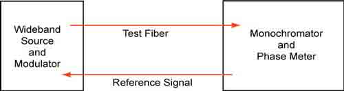
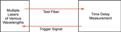
There are several methods used for testing CD in fibers. All involve testing at a variety of wavelengths using several discrete sources of various wavelengths, a tunable laser or a broadband source with a monochromator in the receiver and measuring the relative speeds of the signals. The data taken at discrete wavelengths is then analyzed to calculate the dispersion in terms of ps/nm/km.
Test methods use phase delay or time of flight and generally require access to both ends of the fiber as well as a second fiber for synchronization of the two test instruments at either end. However, an OTDR test method is also used where traces are taken at several discrete wavelengths and CD can be calculated from the data obtained from the traces, allowing testing in the field from one end of the fiber.
All these methods have international standards for the test methods, instruments and data analysis.
| Standards | Description |
|---|---|
| IEC 60793-1-42 | Measurement methods and test procedures—chromatic dispersion |
| ITU-T G.650.1 | Definitions and test methods for linear, deterministic attributes of singlemode fiber and cable |
| TIA FOTP-175-B | Chromatic dispersion measurement of single-mode optical fibers |
| GR-761-CORE | Generic criteria for chromatic dispersion test sets |
Polarization Mode Dispersion
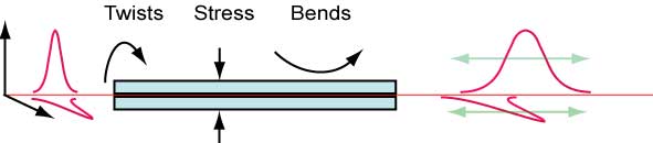
Polarization mode dispersion (PMD) is a bit more complex. Polarization is a phenomenon of light traveling in a medium as a wave with components at right angles. Some materials, like a glass optical fiber, have a different index of refraction for each of those components of the light wave, which is called birefringence. And a different index of refraction means light travels at a different speed, so in the simplest visualization, PMD in fiber looks like the drawing below, where each component of the polarized light travels at a different speed, causing dispersion. The magnitude of PMD in a fiber is expressed as this difference, which is known as the differential group delay (DGD) and called Δτ (“delta Tau”).
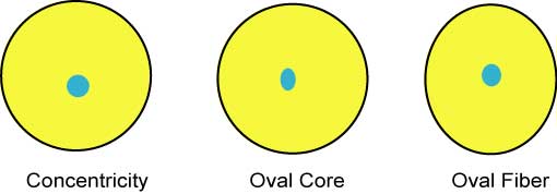
PMD is caused by the birefringence of the fiber which can be influenced by two factors, material birefringence and waveguide birefringence, similar to CD, but more complex. Waveguide birefringence is caused by geometrical variations in the fiber such as concentricity or ellipticity. Material birefringence is mainly caused by stress on the fiber.Waveguide Birefringence
PMD is a complex issue in installed optical fiber. In a long concatenated fiber, each fiber can have different waveguide and material birefringence characteristics caused by the random characteristics of each fiber in the link and variations of the stress on the fiber. Variations are particularly noticeable in aerial fiber, where the PMD may vary considerably according to temperature and wind speed buffeting the fiber!
PMD causes pulse broadening and/or jitter in the received electrical signal, potentially causing errors in the reception of the signals. Since the PMD can vary over time, an extra margin of 1 to 3 dB is often added to the power budget to accommodate variation in PMD.
PMD is an important issue as data rates on long distance links increases to 40 Gb/s and 100 Gb/s. Unfortunately, there are no reliable compensation schemes for PMD, so the only solution is to test links to be upgraded for PMD using one or more of the standardized test methods.
Testing PMD
PMD is generally tested for fibers during manufacture or when being cabled. In the field, it is common to test PMD on newly installed fibers which are intended for operation at high speeds, generally above 2.5 Gb/s or when upgrading fibers installed some time in the past. Since PMD varies over time, a single test becomes an average and tests at a later time may be done for comparison.
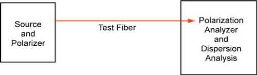
There are a number of commonly used test methods for PMD, some of which are limited to the manufacturing environment, while others can be used in the field. Essentially, all the test instruments have a source which can vary the polarization of the test signal and a measurement unit that can analyze polarization changes.
| Description | Test Method | Standards |
|---|---|---|
| PMD for single-mode optical fibers by the Fixed Analyzer method | Extrema Counting (EC) Fourier Transform (FT) |
FOTP-113 |
| PMD measurement for single-mode optical fibers by Stokes parameter measurements | Jones Matrix Eigen-analysis (JME) Poincaré Sphere Analysis (PSA) |
FOTP-122 |
| PMD measurement for single-mode optical fibers and cable assemblies by Interferometry | Traditional Interferometry(TINTY) General Interferometry (GINTY) |
FOTP-124 |
| Guideline for PMD and DGD measurement in single-mode fiber optic components and devices | FOTP-196 | |
| Measurement methods and test procedures—polarization mode dispersion | Fixed Analyzer measurement method (EC / FT)
Stokes evaluation method (JME / PSA) Interferometry method (TINTY) |
|
| Portable PMD test sets used for analyzing single-mode fiber | GR-2947-CORE | |
| Definitions and test methods for statistical and nonlinear attributes of single-mode fiber and cable | Stokes parameter evaluation technique (JME& PSA) State of Polarization method (SOP) Interferometric methods ( TINTY& GINTY) Fixed Analyzer technique (EC / FT / Cosine Fourier Analysis) | ITU-T G.650.2 |


